So what are you looking to do now?
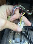
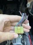
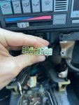
It appears your original radio has a 9-pin connector and a 5-pin connector. I’m thinking the radio you got from eBay uses a 10-pin connector and a 6-pin connector. Is this correct?
So do you want a set of connectors with pigtails to splice into your wiring to give you an ability to use the radio you bought? Or do you want to find a radio that has the same connectors that your original radio has, to use your existing wiring?
I think it was stated before that your existing wiring connectors had 3 sources of power: one being a constant 12VDC source to maintain presets, one switched 12VDC power source for primary power for the amplifier & speakers, and one illumination power source that goes through your interior dash lighting that comes on when the light switch is used to provide dimmable illumination to the radio. Have you verified that all three sources of power are present in your current wiring system connectors? I’m thinking you did, but not sure at the moment.
I’m tied up and away this week and part of next week and don’t have access to my sources of information now. I can generalize but I can’t look up information while away from my sources.