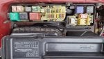
Hi everyone, I have been driving Toyota Celica 6th Generation for the last 20+ years. I am now on my fourth Celica. This one is a 1997 2L GT, ST202N-BLMGF with a 3SGE engine.
![Image]()
I bought her less than a year ago with around 80K on the clock. All the time I have owned her, she has had a strange problem. She always starts cold no problem, but once stopped for more than a few minutes, she refuses to restart, just turns over and over. Symptoms similar to one would expect from vapour lock
When in the no start condition, I know she has spark, as spraying a little starter fluid in the air filter makes her fire up for a few seconds before stalling.
So far I have fitted a new fuel pump, new MAP sensor, new oxygen sensor in the air filter. With no change in the symptoms.
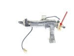
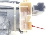
I am now suspecting the fuel pressure regulator. As a split diaphragm, which would loose pressure from the fuel rail could lead to the vapour lock type symptom I am experiencing.
From my chassis number JT164STL200125505 Megazip.net Reckons I need part number 23280 74120, which looks like it screws into the fuel rail:
![Image]()
Despite having bought the Chilton Toyota Celica Repair Manual and after looking very hard several times, for the location of the fuel rail pressure regulator, I have been unable to locate it.
![Image]()
If anyone out there has changed the fuel pressure regulator on thier Toyota Celica Vi ST202 3SGE engine, guidance as to where it is located and how to get to it, would be much appreciated.
Also if any one knows an equivalent part to 23280-74120 that would be very useful as this part is now discontinued and I cannot find one anywhere!
I love this car and want to keep her on the road!
Thanks in advance for your help...
Tony
I bought her less than a year ago with around 80K on the clock. All the time I have owned her, she has had a strange problem. She always starts cold no problem, but once stopped for more than a few minutes, she refuses to restart, just turns over and over. Symptoms similar to one would expect from vapour lock
When in the no start condition, I know she has spark, as spraying a little starter fluid in the air filter makes her fire up for a few seconds before stalling.
So far I have fitted a new fuel pump, new MAP sensor, new oxygen sensor in the air filter. With no change in the symptoms.
I am now suspecting the fuel pressure regulator. As a split diaphragm, which would loose pressure from the fuel rail could lead to the vapour lock type symptom I am experiencing.
From my chassis number JT164STL200125505 Megazip.net Reckons I need part number 23280 74120, which looks like it screws into the fuel rail:
Despite having bought the Chilton Toyota Celica Repair Manual and after looking very hard several times, for the location of the fuel rail pressure regulator, I have been unable to locate it.
If anyone out there has changed the fuel pressure regulator on thier Toyota Celica Vi ST202 3SGE engine, guidance as to where it is located and how to get to it, would be much appreciated.
Also if any one knows an equivalent part to 23280-74120 that would be very useful as this part is now discontinued and I cannot find one anywhere!
I love this car and want to keep her on the road!
Thanks in advance for your help...
Tony